![]()
![]()
![]()
![]()
![]()

|
|
|
TrackPlanning.com NY Signal drawn
|
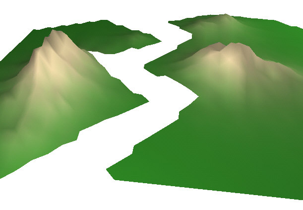
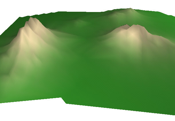
When viewed in 3D, the hills can be seen, as well as the gap between the terrain sheets.
Right-click the boundary of the right terrain mesh (or the edge of an interior triangle). Select Make Contour Line around Mesh to create a Dynamic Contour Line that you can cut into pieces.
Select the Contour Line that now surrounds the mesh. Check the Object Data Window to make sure you selected the Contour Line, not the Mesh. Point to the vertex where you want to slice the line, right-click and select Slice at Nearest Vertex.
In the same manner, slice the Contour Line at the lower vertex.
When the Contour Line surrounding the mesh was first drawn, it had a start/end point at its lower left vertex. Select this contour line and drag it to the side.
Now it's time to edit the left mesh. Because this will be joined to another part of the layout later, the left side of the mesh will be left without a Contour Line. This also demonstrates another command, Open Polygon. This is used to create an opening on the left side. It's an alternative to the Stitching used above to join the head/tail vertices.
Here you can see the opening on the left side of the Contour Line. To remove the unwanted vertices on the left side, double-click the Contour Line to edit it.
Delete all the vertices on the left side, leaving only the important ones for the peninsula. Double-click to end the Contour Line edit session.
Right-click the Contour line near the upper vertex that divides the side from the center. Choose Slice at Nearest Vertex as shown.
In the same way, right-click the Contour line near the lower vertex that divides the side from the center. Choose Slice at Nearest Vertex as shown.
Now use the standard Connect Terrain tool to join the center two contour lines. You can see how the terrain is properly color to reflect the elevation changes in the two meshes.
Press Tab to swap to 3D, and see the results of the connection. The seam is barely visible and the terrain flows smoothly from one mesh to another.
|
|
Send mail to webmaster@TrackPlanning.com with
questions or comments about this web site.
|

 This is the starting
point. Two oddly-shaped terrain meshes were drawn using freehand outlines. They
were each edited in the Terrain Editor. Around them is the benchwork edge that
forms the peninsula we're designing. There's also a Light in the drawing - this
is important, so you can see the changes as you edit in 3D.
This is the starting
point. Two oddly-shaped terrain meshes were drawn using freehand outlines. They
were each edited in the Terrain Editor. Around them is the benchwork edge that
forms the peninsula we're designing. There's also a Light in the drawing - this
is important, so you can see the changes as you edit in 3D.